Demo Vision Box
Set up the demo vision box using its camera, lighting and optional side-camera adjustments.
The demo vision box has manually adjustable cameras and lights for inspecting parts of different shapes and sizes. Use the adjustments below to frame the inspection area and control how it is illuminated.
Work area and part size
The 400 x 400 mm backlight is the nominal optical work area and a reference for placing the part. It is not the maximum part size: a larger part can be inspected if it fits inside the box and the doors close completely during operation.
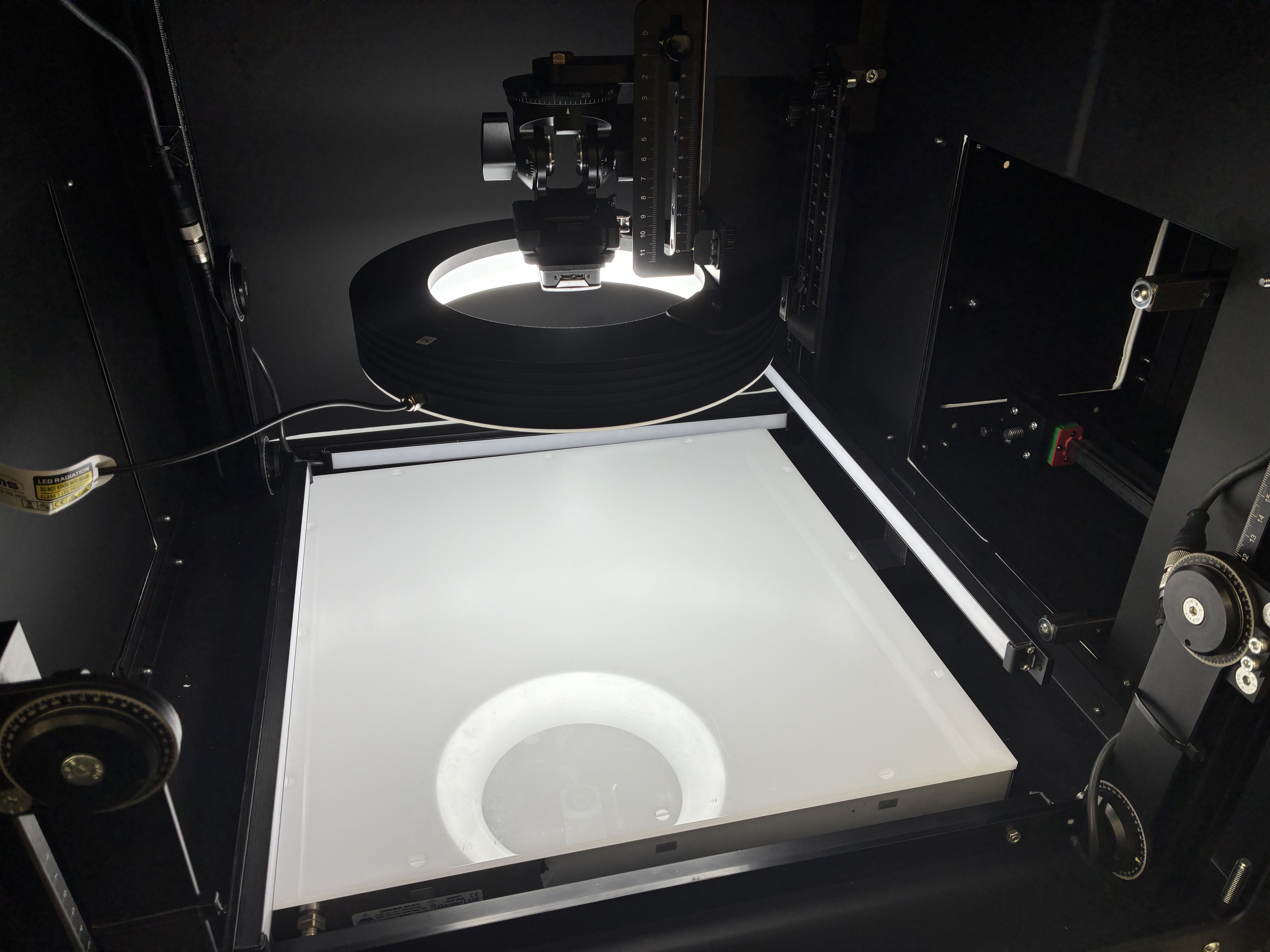
Backlight and interior work area.
Main camera and ring light
The main camera and ring light sit on linear slides. Move the assembly in the horizontal plane to center the area you want to inspect, then set the height of the light and the camera separately.
| Adjustment | Available travel | What it changes |
|---|---|---|
| Assembly, X | 300 mm total (up to 150 mm either side of the box center) | Horizontal position of camera and ring light together |
| Assembly, Y | 300 mm total (up to 150 mm either side of the box center) | Position of camera and ring light together along the other horizontal axis |
| Ring light, Z | 230 mm total (two consecutive 115 mm slides) | Height of the ring light and the camera assembly mounted on it |
| Camera relative to ring light, Z | 230 mm total (two additional 115 mm slides) | Camera-to-light distance without moving the ring light |
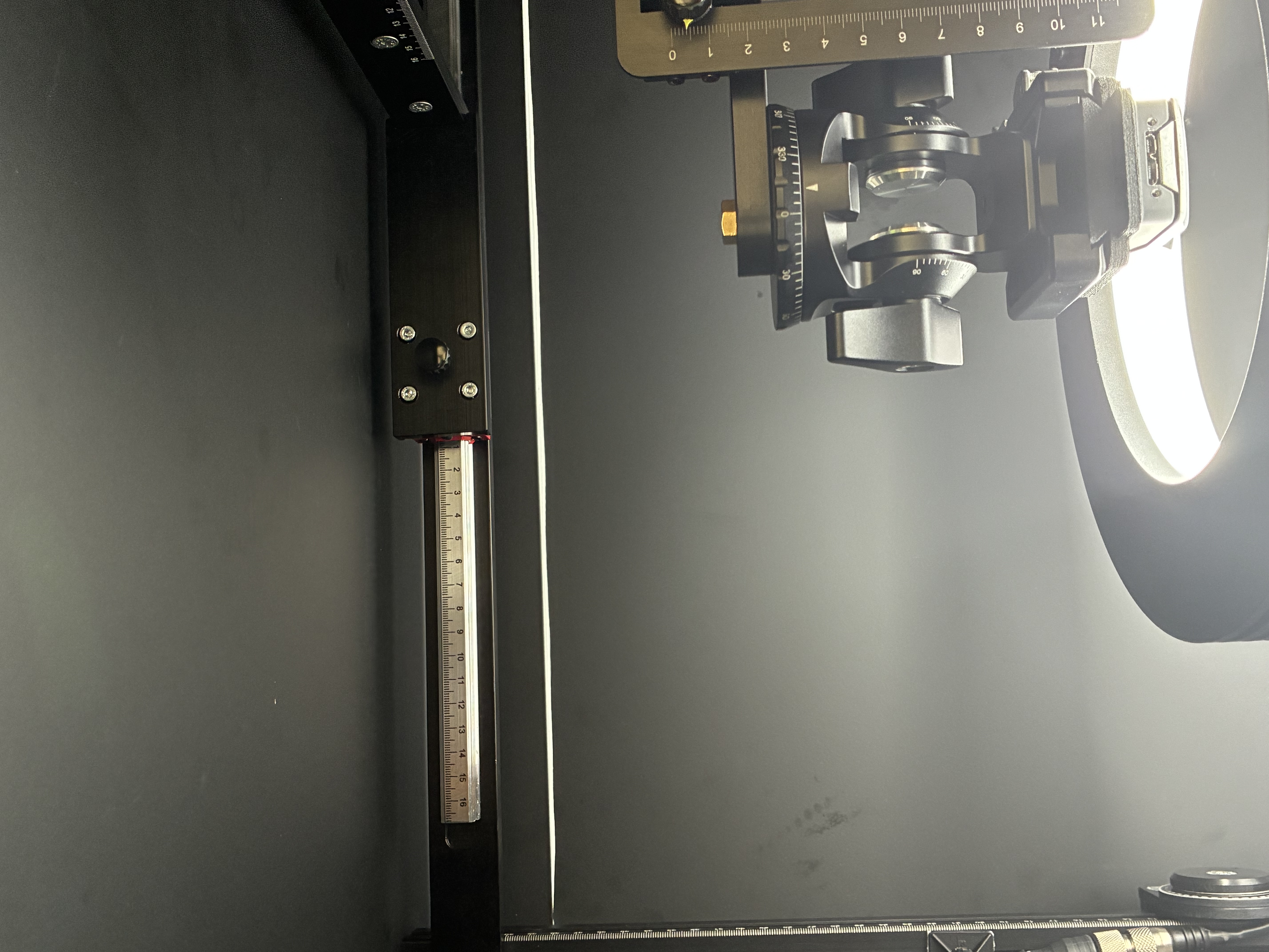
Main assembly: X-axis slide and graduated scale.
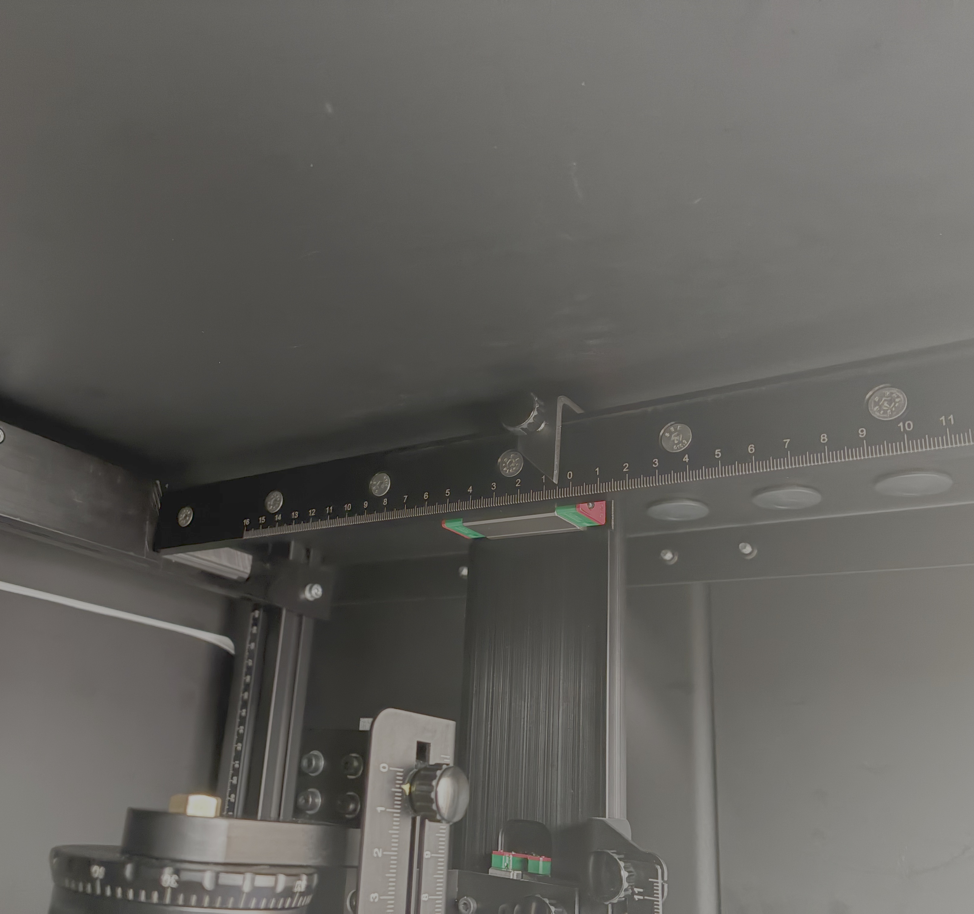
Main assembly: Y-axis slide and graduated scale.
The X and Y adjustments cover a 300 x 300 mm positioning area centered on the box. The four vertical slides are arranged in series: the two ring-light slides and the two camera slides give the main camera up to 460 mm of combined Z travel. This is not an extra 460 mm adjustment on top of those slides. Adjusting the ring-light slides moves the camera with the light; adjusting the camera slides changes their relative spacing.
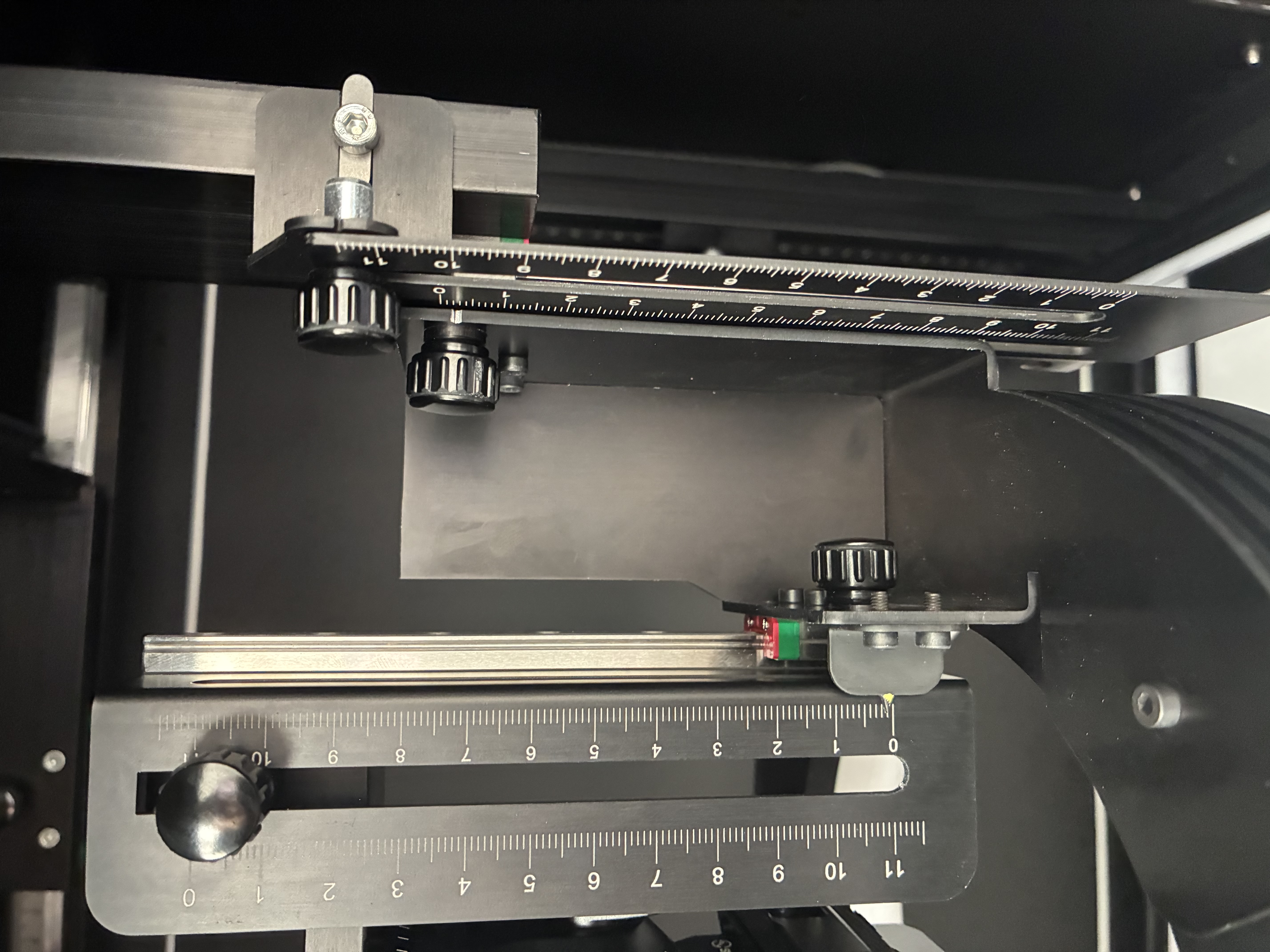
Separate Z adjustments for the ring light and main camera.
To reposition any linear slide, loosen its knob or locking lever, move the component by hand, then tighten it again at the desired position. Do not leave a slide unlocked after adjustment.
Bar lights
Each internal bar light can be raised or lowered along its aluminum support profile. Use the graduated scale as a reference when setting the height or reproducing a previous lighting arrangement; secure the height with the corresponding knob or locking lever. No fixed vertical travel is specified for these lights.
You can also rotate each light’s articulated arm to aim the beam at the inspection area. The arm holds its angle through spring-generated friction: there is no angular locking knob. Set the height first, then change the angle to vary the direction and incidence of the light on the part.
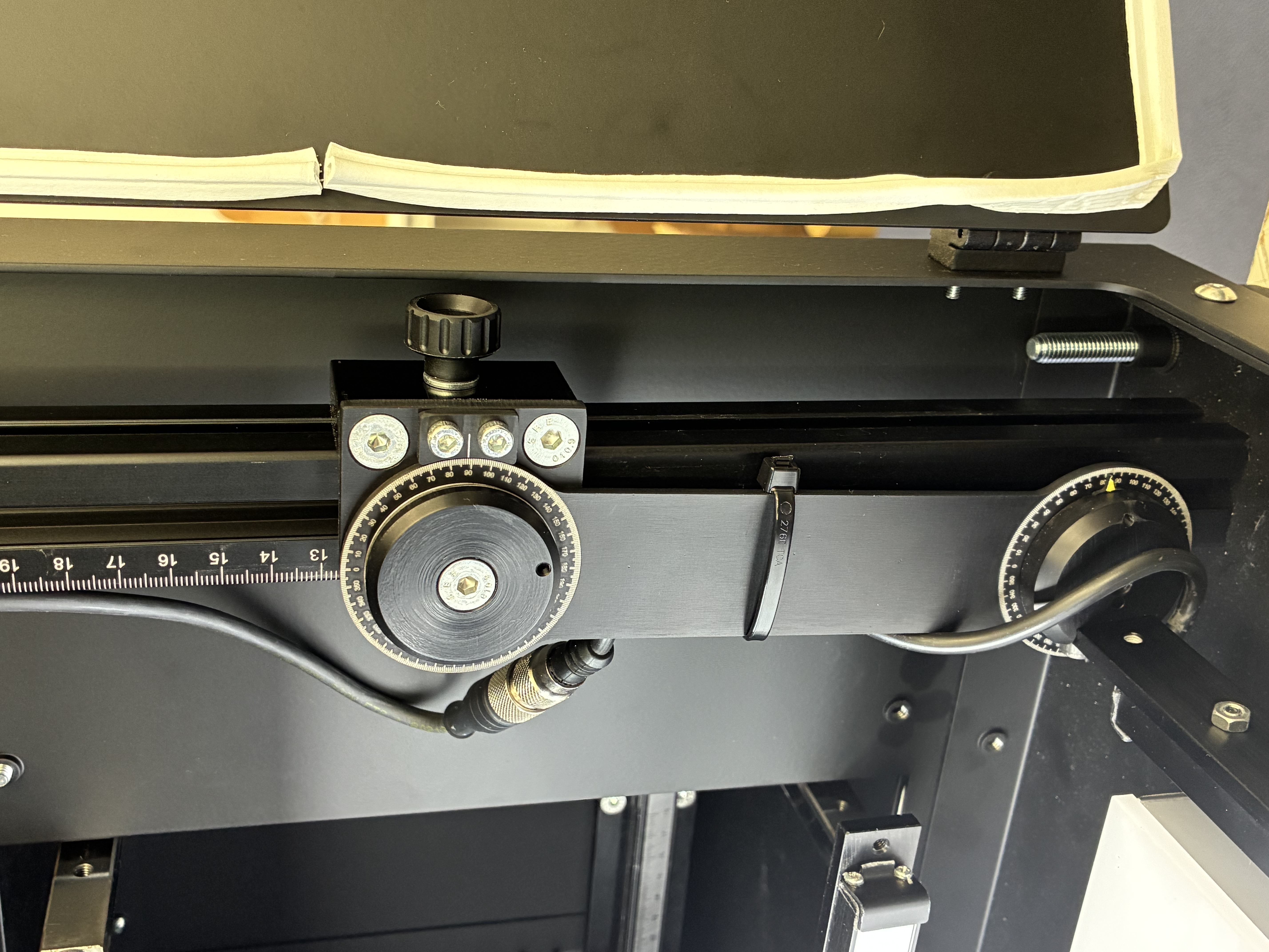
Bar light: vertical slide, graduated scale and adjustable arm.
Optional external cameras
The box can accommodate one or two additional external camera supports, one on each of the two side walls without the large access doors. These positions normally have a cover plate held by four screws. To fit an optional support, remove those screws and the plate, then attach the support to the structure using its four side mounting brackets. Only install the accessory supplied for this box.
Each external camera support has its own X, Y and Z position adjustments and a movable, aimable mount. Use these to bring the camera into position and point its optical axis toward the part. With two supports, the side cameras face each other from opposite sides of the box. The report does not specify numerical travel ranges for these optional adjustments.

Side position for an optional external camera support.
Adjustment reference
| Component | Movement | Locking or position holding |
|---|---|---|
| Main camera and ring light | X and Y, 300 mm per axis | Knob or locking lever |
| Ring light | Z, two 115 mm stages (230 mm total) | Knob or locking lever |
| Camera relative to ring light | Z, two 115 mm stages (230 mm total) | Knob or locking lever |
| Main camera | Combined Z travel, up to 460 mm | Knobs or locking levers on the four slides |
| Bar lights | Vertical sliding; graduated height reference | Knob or locking lever |
| Bar-light arms | Continuous angular adjustment | Spring-generated friction |
| Optional external cameras | X, Y, Z and aim | Manual adjustments and aimable mount |
Set up an inspection
- Place the part on the backlight and check that the doors can close fully.
- Use the X and Y slides to position the main camera and ring light over the area of interest. Set their height and camera-to-light spacing with the Z slides, then lock each slide.
- Set the bar lights’ height against the graduated marks, lock the vertical adjustment and aim their articulated arms at the area to inspect.
- If fitted, position and aim the external cameras for any additional side views.
- Close the doors. Check the live image in the Camera module on BIION-D Edge, adjust framing and lighting as needed, then run the pipeline. Check for glare, shadows and missing details before repeating the inspection with this setup.